Please sign in so that we can notify you about a reply
Description
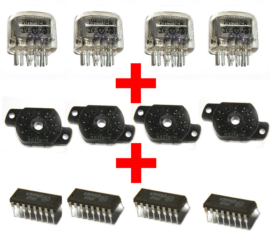
4 x IN-12B + 4 x SOCETS + 4 x Drivers K155ID1 NEW NIXIE TUBES NIXIE CLOCK F/SH NEW NIXIE TUBES BRAND NEW! CHEAP! BEST
FREE SHIPPING
Payment Details:
We accept the following payment methods:
Visa/MasterCards/EuroCards via PayPal.
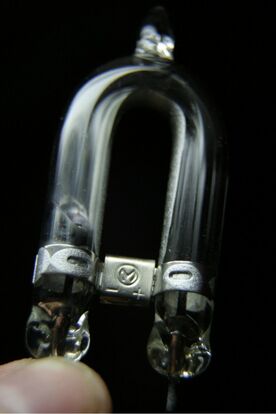
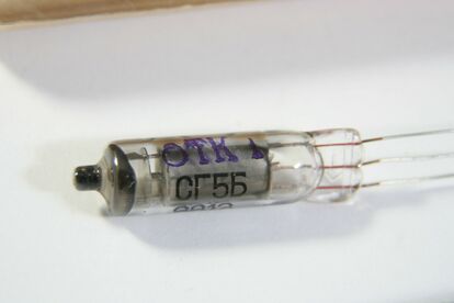
IN-12A
D e s c r i p t i o n
Nixies is made in USSR. New, old stock. Rare, not produce now IN-12 isThe cold cathode of these devices has the form of Arabic numbers from 0 to 9
This listing is for
4 x IN-12A
+ 4 x SOCETS
+ 4 x Drivers K155ID1
Tube size: 19mm x 55mm (0.76” x 2.2”)
Symbol height: 18mm (0.72”)
Supply voltage: 170V
Working current: 2.5mA
Electrical parameters
Brightness
>=100cd/m^2
Angle of visibility
>= 90 deg
Power supply voltage
>= 200 V
Discharge appearance voltage
<= 170 V
Discharge voltage:
<= 150 V
Display current
<= 4 mA
Operations current: Running from DC
4 - 7 mA
Running from AC with 50 Hz (average value)
2 - 4 mA
Life time
>= 5000 hours
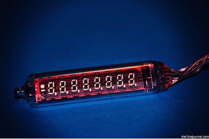
The clock on thedischargeindicatorIN-12
Previously,theseindicators arewidely usedfor displayingdigital informationin measuring instruments, etc., but now theurgency ofthis decisionis questionable,however, studiedan appropriate topicof our forumand ranaccording tothe linksin it,was madea willfuldecision topileon thebasis of themonkwatches ...What,in your sparetimefrom the basiclessons, and it wasslowlyrealized.
Some sort ofstructuralscheme of the deviceshown inthe picture:
In the diagram,the redarrows show thedata bus, andblue- power supplyunits.
Hours canbe powered fromseveral independentsources,which areisolatedby usingSchottky diodeswith alow drop-D1-D6.As aninput tothe first power supplyis installedMOLEXconnectorthatallows you to usea computerpower supply, the second inputis designedas aconventionalcoaxialDC / DCjack, and the thirdsource is theAC / DCconvertercircuit iscourtesy ofmy colleague(unfortunately, it does notregisteredon the forum)and is presentedbelow:
he scheme is simple, but there are nuances: a diode VD1 - fast (if you use the chip IR2153D it is not required), suppressor VD4 and VD15 are necessary to protect the rectifier diodes, if they are selected without a large supply of voltage. Transformer Tp2 made three put together ferrite rings size 20h12h6 2000NN: primary winding contains 70 turns of 0.3mm, low-power secondary winding (for supply IR2153) - 2 sections of 7 turns of the same wire (two wires dangle, then the beginning of one wire is connected with the end of the other and get the average point - as usual), a powerful secondary winding - 2 Section 7 turns of three wires braid 0.5mm (6 wires shakes, then divide in half, etc. - as well as with low-power). Do not forget the interlayer insulation!
Radiators for transistors for power to 15-17 watts is required, though the board provides a place for them. Resistor R1 represents three series-connected resistor to 100k each.
Input filter: TP1 and capacitors C1 and C2 - is taken as is from the ATX power supply, inductor L3 is wound on the ring of the output inductor of the same power supply (simply wrapped wire MGTF in a single layer - much climbed, but can be up and ready again to take .. .)
For definiteness, assume that after the diode junction voltage is 12V.
For the digital supply voltage must be 5V clock, which is obtained from the 12V with a pulsed DC / DC converter, which was built based on the chip TL2575-05 from Texas Instr.:
To supply thegas-dischargeindicators requirea high voltage sourceof the order of200Vneeded forignition andmaintain a stablelevelin the indicator.Upconverter12 ->200Vis madeon a chipMAX1771:
In the high-voltage part of the circuit elements should be used to withstand appropriate voltage. Divider formed by resistors R2, R3 and variable resistor sets the output voltage, which can be adjusted within certain limits. In my case, the output voltage is 190V, which is sufficient for the indicators. Inverter power is sufficient for simultaneous operation of all six indicators.
I advise you to be careful when debugging: 200V - high voltage, and even isolation from the mains is present, and the power converter is not great, he was pounding on the paws quite well ...
Structurally, these DC / DC converters to save space and for a number of other considerations presented in the form of individual vertical circuit boards and soldered to the motherboard clock:
On the left - a 5-volt converter to the right - increases. The decoder is used to convert the data stream it receives from the MC, to a form suitable for display on the display. The scheme of the decoder along with the display shown in the figure:
To display data on the display are loaded in four series-connected 74NS595 register. In the last register in the chain store data corresponding to the decimal point of the display, its output is directly controlled high-voltage switches Q1-Q6, which, in turn, ignite or extinguish the appropriate decimal point.
Younger 4 digits of the other three registers contain the binary code that corresponds to the odd character cells display (1, 3, 5), and senior nibbles - even (2, 4, 6). This code is supplied to the inputs of the binary-decimal decoder with a high yield K155ID1 that control directly to the indicators. In the plate circuit of each indicator is set current-limiting resistor. Since the current is much smaller than the current point of any of the digits of the indicator in the chain of reservoirs "point" of transistors installed additional resistors. Thus, because the register is only updated by the team manager of MK and changes occur only on certain lines of data, we have actually a static display, although the update of the display is 20 times per second.
The block itself consists of the microcontroller MC, real-time clock M41T80M6 from STMicroelectronics, USB FT232BM module for communication with a PC drive level RS-232 interface chip MAX232 for the same purpose, and control buttons. The scheme of all this happiness, as usual, is shown in Fig.
USB moduleto theFT232BMis a separatefee,verticallysoldered intothe main.Module isassembledonthe templateexcept for themissingchipEEPROM:
At the same time can only run one of the COM interfaces or USB, with preference given to USB, because switching is realized by means of the relay, energized from the connector USB: sticking with cable relay will spread and go to the controller data from the module FT232.
Generally, the interface converter USB <-> RS232 can be found in this article, and tell you a secret that in the final version of the clock is a converter on the TUSB3410, but it has been said about the priorities of interfaces is true for him ..
Structurally, the building designed in hours on the computer CD-ROM and consist, as already noted, several of the boards. The whole area of the body is the main circuit board that is mounted inside the housing to regular seats, the rest of the "native" card CD-ROM. It installed a network power supply, a microcontroller with a clock, all necessary connectors and a part of the decoder chip. The rest of the decoder chip mounted on a separate board that is installed on the main board, second floor. The power modules vertically soldered to the main board.
The back panel connectors are installed between the 4 buttons that serve to adjust the hours and mode selection.
This is how it all vygyadelo during debugging:
Itis connectedonly toadditional chargesdecoder,the main boardyet.
Fullyassembledboardclock:
Thus, the constructs with little understood, now a few words about the firmware.
Controller - ATMega8515. Such a choice is made only because they have me. In principle, the code is easily ported to ATMega16 (only need to remove the definition of port E, and a couple of nuances).
The controller reads data from the chip through the RTC bus I2C, engaged in loading data into registers, monitors the status of the buttons and listen to UART - as a whole, all as always.
Clock can display the actual time (in HH: MM: SS or HH: MM), the date in the format DD: MM: YY, start counting seconds: SS, have an alarm clock, and can also be used to display numerical information flowing through a COM or USB.
Control is the buttons, as already mentioned, the rear of the enclosure. For each button you can "hang" the implementation of four functions called short or long pressing on the pressing 1, 2 or 3 seconds. Long pressing the supported one, two or three short beeps, respectively.
The functions assigned to the buttons as follows: A. Pressing 1 on 1s - to set an alarm clock. The screen displays the current alarm set time, the discharge hour is flashing. Buttons 3 and 4 are used to decrease / increase the reading, the new value is confirmed by pressing a buzzer and then starts flashing digit minutes, setting the value of which is similar. If you do not perform any action after the entrance to the installation procedure, after a while the clock returns to native mode. Two. Pressing 1 for 2c - Set time and date in the following order: hour, minute, year, month, day. Setup is similar. Three. Clicking on a 3s - Service settings: Mode display the time (1 or 2 - HH: MM: SS or HH: MM), the show dates, in seconds, time display of data from your PC in seconds (unless within that time the PC is not new data arrive, the clock will return to the main mode) 4. Short press button 2 - showing the date for the time configured in the service menu, and then clock back to normal Five. Short press the 3 button - on / off mode of the second point: the screen shows only a second. 6. Pressing 3 for 1s - on / off indication. 7. Pressing 4 on 1s - on / off alarm clock (with alarm clock in the senior category displayed decimal point).
All settings are stored either in volatile memory chip clock, or in non-volatile memory IC, so that when power is saved.
When the alarm buzzer will sound for as long as you press any button.
I am very satisfied with this seller. He had patience with me and patiently answered all my questions. Everything was done to the max and the delivery to Europe was very fast.
Jovana06/17/2023, 01:58
Excellent product, good communications, fast shipment! thank you, will buy again
MARA OKSHTEYN11/21/2022, 11:24
Order was in good shape when it came in. Included paper manual is in Russian but electronic version is in English and unit was programmed to English. Attachments were as ordered and were in good shape. It took just over 5 weeks from ordering to arrival, but given the significant challenges the country is in, this is realistic. Seller was responsive to questions. Had to pay extra shipping here given the current challengs.
Jeff Gibbs06/21/2022, 14:01
The Seller was friendly and cooperative and my order eventually made it through. Shipping for the order leaving the Ukraine was substantially delayed, probably due to the war. Ordered 22 Apr; shipped Apr 26, processed April 29, finally processed by mail destination in Kiev May 27, finally received June 9. The order was as expected other than the add saying it would include an English manual and Practical Guide and that was not what arrived, and I was not notified of the change. Hence the 4 star rather than 5 star rating. The manual that was received is in Russian not English, and no practical guide was included. I suspect that the seller is doing his best under extremely challenging circumstances and shipping delays due to the postal service are outside his control.
Jeff Gibbs06/09/2022, 14:47
pretty good and excellent considering the circumstances.
may we all live in uninteresting times
go well
tony belligoi australia 03/04/2022, 16:02
Great fast service!
Gene Jackson02/26/2022, 02:00
Everything was OK, thank you!
buyer08/23/2021, 06:07
great service, they went out of their way to expedite shipping to me. Highly recommended group of people to deal with. A++
randy crough12/23/2020, 07:16
Shipping and Policies
Payment
This store is integrated with the Western Bid™ e-commerce platform, and Western Bid, Inc. is the Merchant of Record for all purchases made in this store. Therefore, you will see "WESTERN BID" listed as the payee on your PayPal account and credit card statement.
I accept PayPal or Credit Cards only. • Your items will be made and shipped only after the payment is cleared. • If you don't have Paypal account and would like to pay with your Credit Card, check this step-by-step tutorial on PayPal: https://www.paypal.com/webapps/mpp/pay-online
Your order will be shipped only after the payment is cleared. This means if you pay via Paypal e-checks there could be delay in 3-5 business days. You can check the status of your payment in your Paypal account or in the correspond invoice here on Lavky.
Shipping
All the items in the order will be securely packed and shipped within 1-3 working days of payment. Some items may take longer. If the processing time is more than 7 days, it is clearly stated in the product description.
Delivery Address:
• Please make sure your shipping address is correct at the checkout.
We will ship your order to the address specified on Lavky.com checkout, and not to the address specified on Paypal.
Terms of Delivery
We always ship parcels with a tracking number. We will update you on the tracking number once your order has been prepared and shipped.
Usually delivery takes between one a half and four weeks.
Please note that delivery times may vary depending on your location and customs clearance, so we cannot guarantee the exact time of arrival.
Here are the approximate delivery times:
- USA: 1.5 - 2.5 weeks
- Canada: 2-3 weeks
- Europe: 1-2 weeks
- Australia: 2-3 weeks (sometimes longer, depending on Australian customs)
- The rest of the world: 2-3 weeks
Delivery method
We ship all the parcels from Ukraine (from our logistics centers in Kyiv and Chernivtsi) via international services (FedEx, UPS) in two stages.
First a parcel is sent by express delivery service to Europe, and then, it is shipped by air mail to the United States, Canada or Europe.
You can see the movement of the parcel by a tracking number only in the second stage - 4-6 days after sending your order from our center. We estimate the delivery time to 12-18 days.
Express delivery is available only on individual request. Please contact us if you need Express delivery before placing an order so we can update shipping options.
Customs duties and taxes
Customers are responsible for any fees, taxes and duties related to delivery and ordering products to their country of destination.
Packaging
Your order will arrive in a safe cardboard box, with due packaging and protection from damage.
Refunds and Exchanges
I want my clients to be happy, so let me know if you have any problems.
If you are not satisfied with your items / service for any reason, please contact me with the problem before leaving a feedback.
Related products
Our website uses cookies to improve your user experience. If you continue browsing, we assume that you consent to our use of cookies. More information can be found in our Privacy Policy.